
Petrol forecourt canopy design 12 × 18 m starting form
Explore the relationship between roof, dispenser positions and vehicle space. This roof-only concept is a visual coordination starting point for a fuel forecourt brief, with the steel frame and bracing kept visible.
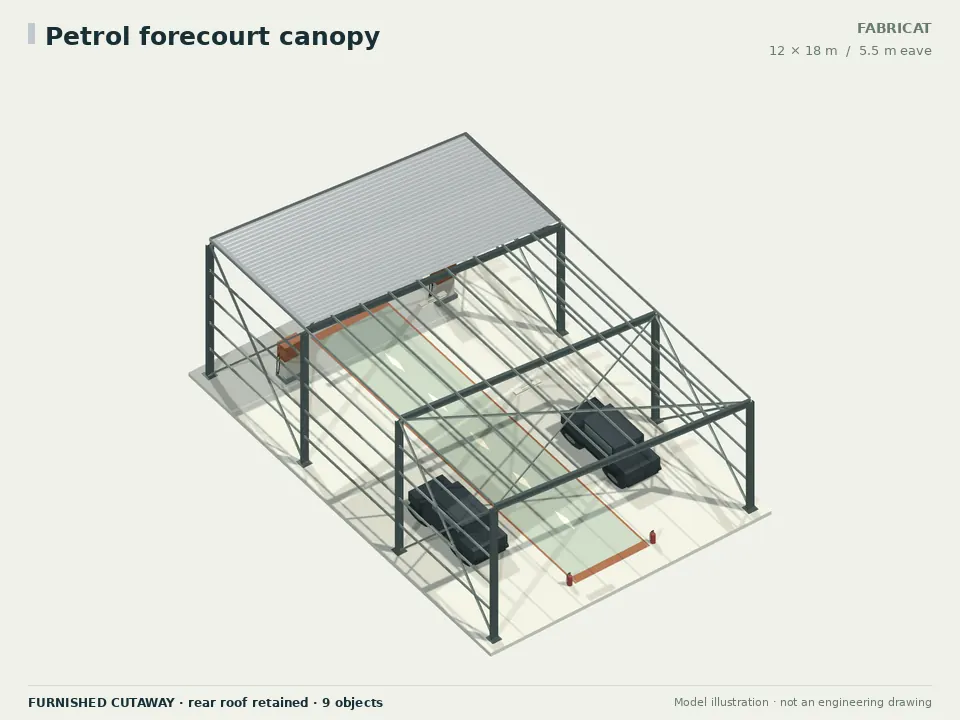 FURNISHED CONCEPT
- Floor footprint
- 216 m²12 × 18 m width × length
- Eave height
- 5.5 mCheck actual underside clearance
- Bays along the length
- 3 bays6.00 m centre-to-centre
- Wall arrangement
- Open sides · no wall claddingStructural members remain at openings
See what changes the steel quantity.
The range compares 2, 3, 4 bays at the same width, length, eave, roof, openings and selected sections. It describes those modelled arrangements; it is not an engineered minimum–maximum allowance.
Concept take-off, sections not designed — run the section sizing screen
Starting 3-bay model: 8,456 kg of modelled steel.
See exact scenarios and quantity basis
| Bays | Bay spacing (m) | Model steel (kg) | kg/m² | kg/sq ft |
|---|---|---|---|---|
| 2 | 9.00 | 7,454 | 34.51 | 3.206 |
| 3starting | 6.00 | 8,456 | 39.15 | 3.637 |
| 4 | 4.50 | 9,558 | 44.25 | 4.111 |
Primary / secondary / brace sections: BSP MB 300 × 140 · MC 100 × 50 · ISA 75 × 75 × 6
End-wall framing is enabled, matching a fresh editor preset; modelled end posts are included where walls are clad. This is net frame, secondary-member and plate mass. Procurement waste, cladding, civil works, furnishings and equipment loads remain separate. No price, safe capacity or design approval is inferred.
A furnished starting layout.
The current fit-out generator places 8 physical objects in this starting model. These counts come from that generated layout.
- 2Generic service vehicleVehicle envelope
- 2Fuel dispenser conceptDispenser concept
- 2Linear light fixtureGeneral light
- 2Extinguisher positionFire equipment position (review required)
The 3.5 m central stripe is a planning reserve, not an approved exit route or vehicle swept-path result. Equipment is generic; confirm capacity, service clearances and actual loads separately.
Questions, answered.
A closer look at the petrol forecourt canopy concept, its editable inputs and the decisions that belong in a project-specific design.
What are the starting dimensions of the petrol forecourt canopy?
The preset starts at 12 m wide by 18 m long, with a 5.5 m eave and 3 bays along its length. You can edit these dimensions. They describe a concept starting form, not an operating capacity or approved structural design.
Is this an approved fuel-station layout?
No. The roof, dispenser and vehicle objects are generic geometry. Fuel storage, hazardous areas, setbacks, fire provisions and approvals require specialist design for the actual site.
Are the dispenser objects tied to a supplier?
They are generic spatial references without manufacturer or capacity claims. Replace their dimensions and service zones with the selected equipment supplier's drawings.
Does the canopy provide a clear vehicle route?
Column and brace locations remain part of the portal-frame concept. Verify actual vehicle swept paths, height limits, queueing, pedestrian movement and dispenser access in the site plan.
Does the steel quantity cover the whole petrol station?
It covers the modelled building-frame scenario only. Tanks, pipework, dispensers, forecourt paving, electrical systems, signage and other facility works are outside that quantity.
Related shed concepts.
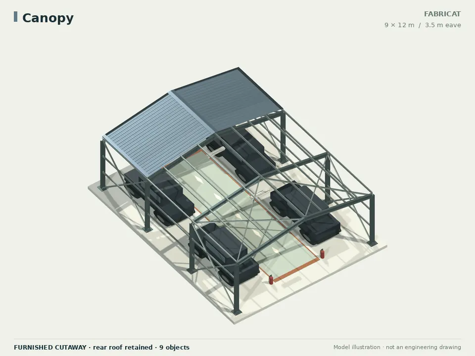
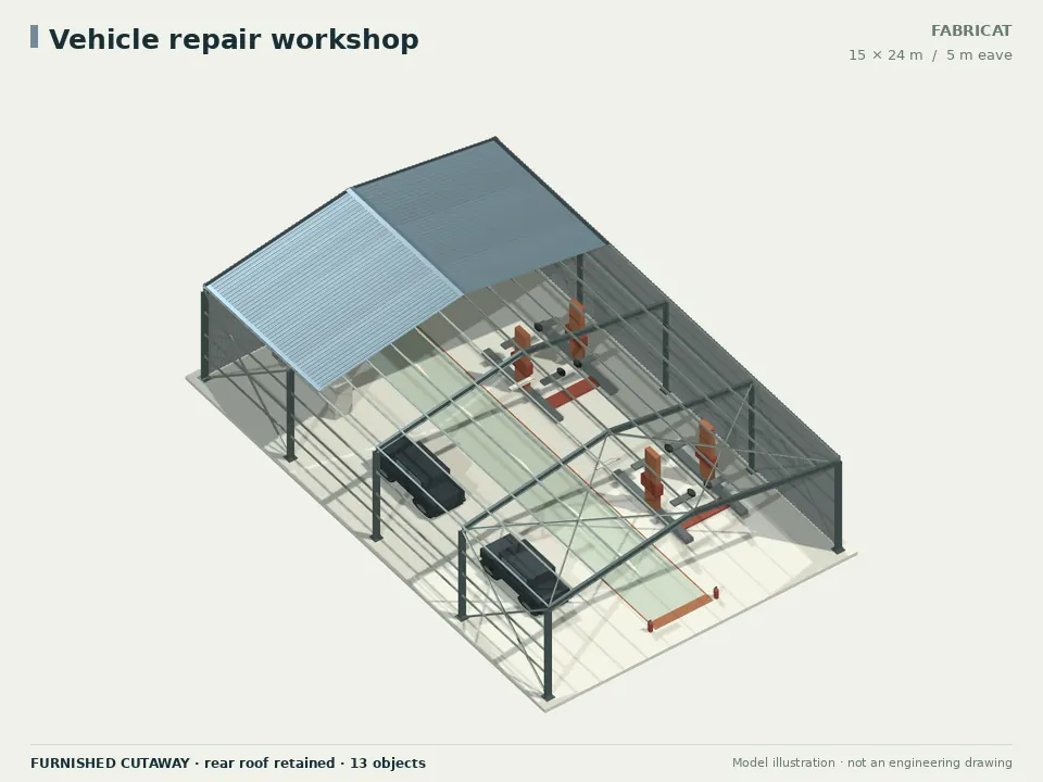
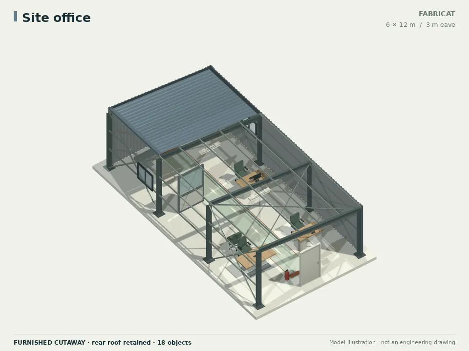
Make this starting point your own.
Adjust the dimensions, roof, enclosure and equipment layout. Keep refining the actual project brief and engineering inputs alongside the model.